Air Refueling the A-12 and SR-71 Blackbird
Here are a bunch of pictures of aerial refueling with the Lockheed SR-71 Blackbird and A-12 Oxcart. Feel free to leave comments below about your experiences and as always, please email me your pictures at the email address listed to the right. 


SR-71A #61-7952 during the first ever in-flight refuelling of an SR-71, on 29April1965. Lockheed photo via Tony Landis


KC-135 Refueling SR-71 Blackbird at sunset.


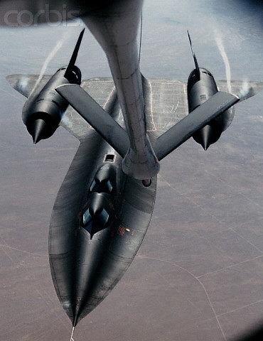
ca. 1991, NASA Dryden Flight Research Facility, Edwards Air Force Base, California, USA — NASA’s triple-sonic SR-71B experimental reconnaisance jet flies up to the refueling probe from an aerial tanker near Edwards Air Force Base, California. 1991. — Image by © CORBIS

KC-135 refueling M-21 with GTD-21 Drone.


Close up view from the Boom Pod while refueling a SR-71 Blackbird.

Post AR with an SR-71.


A left side view of an SR-71 aircraft moving toward a KC-135 Stratotanker aircraft for inflight refueling. The SR-71 is from the 9th Strategic Reconnaissance Wing.


Lockheed SR-71 in flight refueling. SR-71A (S/N 61-7952) refuels from KC-135A (S/N 58-0094). (U.S. Air Force photo)
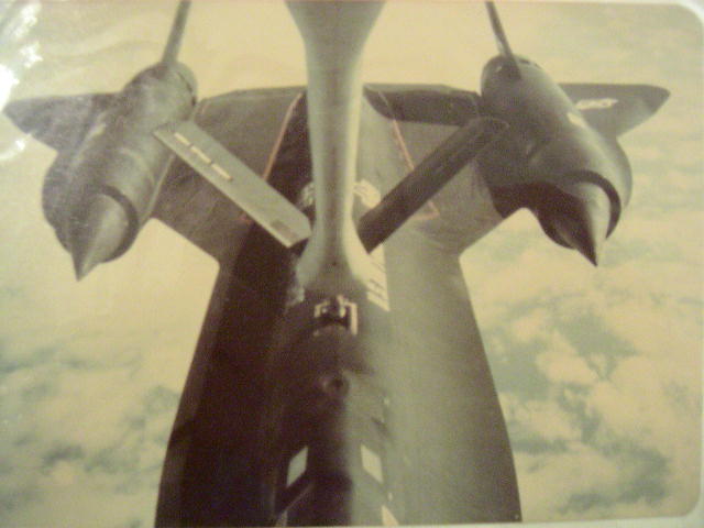


Image Source:
Various
Boom Operator Memorial – Altus AFB, OK
This memorial is a lasting tribute to those who gave the last full measure of devotion that freedom might survive lost in the steadfast performance of duty they, their crews, and families have the gratitude of an eternally thankful nation. It is with solemn pride and a heavy heart that we acknowledge these who have laid so costly an offering upon the altar of freedom and ensured we shall never forget their sacrifice.
Boom Memorial Names |
| KB-29 SUPERFORTRESS | |
| 7-Jul-51 | TSGT HENRY H. HILL |
| 7-Jul-51 | 1LT JACK W. KERN |
| 7-Jul-51 | CPL REGINALD F. RUSSELL |
| 7-Jul-51 | SSGT SCOTT L. WALLACE |
| 10-Jul-53 | SGT WALTER F. OLSEN |
| 26-Dec-56 | TSGT THURMAN RANIER |
| 10-Jan-57 | TSGT EDWARD C. CLEMONS |
| 10-Jan-57 | SSGT MICHAEL B. MCINTOSH |
| 2-Feb-57 | MSGT LAWRENCE M. GRIGORY |
| 2-Feb-57 | A2C ARTHUR B. KOSIER |
| 2-Feb-57 | A3C FRANKLIN D. SCHWEIGERT |
| KB-50 SUPERFORTRESS | |
| 13-Mar-57 | A2C ROBERT E. CRAIG |
| 13-Mar-57 | A2C BILLY B. ROSE |
| 8-May-57 | SSGT THOMAS E. O’CONNOR |
| 8-May-57 | A3C DONALD E. COSPER |
| 13-Aug-58 | A2C FRANCIS C. HERMANCE, JR. |
| 13-Aug-58 | SSGT NORBERT T. KNULTY |
| 22-Jan-59 | A2C IGNACIO W. SANCHEZ |
| 22-Jan-59 | TSGT WAYNE M. SOUDER |
| 4-Aug-59 | A2C THOMAS M. PAYTON |
| 18-Oct-60 | SSGT HARDIN A. BAILEY |
| 18-Oct-60 | A2C THOMAS J. LANE |
| 18-Oct-60 | A3C MICHAEL W. MILLER |
| 5-Mar-61 | SSGT HAROLD D. MEEUSEN |
| 5-Mar-61 | A2C CLIFTON C. TABOR |
| 8-Jan-62 | A2C PAUL M. CLAWSON |
| 8-Jan-62 | A2C CARLTON A. LINK |
| 8-Jan-62 | SSGT BILLIE D. MOORE |
| 9-Feb-62 | A1C GUY L. POWELL |
| 9-Feb-62 | A2C RALPH E. REUTZEL |
| 20-Dec-62 | SSGT ROBERT T. CRAIG |
| 20-Dec-62 | SSGT JAMES R. HAYES |
| 13-Aug-64 | SSGT WALTER B. HICKMAN, JR. |
| 13-Aug-64 | SSGT CAREY A. LIVINGSTON |
| KC-97 STRATOFREIGHTER | |
| 9-Nov-51 | SGT JAMES A. MAINS |
| 27-Jun-54 | A1C DAVID ARAMBULA |
| 27-Jun-54 | SSGT ROBERT O. GONZALES |
| 27-Jun-54 | SSGT VINCENT PROVENZANO |
| 23-Feb-55 | SSGT ROBERT E. ROSENCRANCE |
| 23-Feb-55 | A2C CHARLES J. SITFA |
| 4-May-55 | A1C MARVIN R. DEVRIES |
| 4-May-55 | A1C JOSEPH L. PRIDGEN |
| 13-Jul-55 | SSGT GEORGE R. MIGNOSA |
| 13-Jul-55 | SSGT MARVIN F. RUSK |
| 25-Apr-56 | SSGT DONALD S. DELPRIORE |
| 25-Apr-56 | A2C JURI E. JOONAS |
| 25-Apr-56 | SSGT KENNETH E. VANPATTON |
| 26-Jun-56 | TSGT BARDEL A. CRUM |
| 26-Jun-56 | SSGT ROBERT L. WALLACE |
| 6-Jul-56 | A2C WILLIAM L. FALCONER |
| 22-Jan-57 | SSGT JOEL V. BLACKWELL |
| 22-Jan-57 | SSGT RAYMOND E. NOAH |
| 18-Jul-57 | SSGT JACKIE J. JAMERSON |
| 29-Oct-57 | TSGT RONALD E. RUBLE |
| 12-Nov-58 | MSGT CURTIS W. KING |
| 12-Nov-58 | A2C JOHN M. SCSERBAK |
| 22-Jul-59 | TSGT JAKE SCHMIDT |
| 30-Mar-60 | SSGT SHIRLEY D. RENNER |
| 27-Jun-60 | TSGT ROBERT P. COSTELLO |
| 28-Feb-61 | SSGT ERNEST J. LEMOINE |
| 5-Nov-64 | SSGT GERALD W. SHULTZ |
| 19-Dec-64 | TSGT JAMES R. BILL |
| KC-135 SRATOTANKER | |
| 27-Jun-58 | MSGT DONALD H. GABBARD |
| 25-Nov-58 | TSGT RONALD L. CHAMPION |
| 31-Mar-59 | TSGT HERMAN A. CLARK |
| 15-Oct-59 | SSGT PAUL R. THOMASSON |
| 3-Feb-60 | SSGT GEORGE W. SHORT |
| 9-May-62 | SSGT WALLACE R. ADAMS |
| 10-Sep-62 | TSGT JOHN L. DUNCAN |
| 10-Sep-62 | TSGT KENNETH A. QUINN |
| 27-Feb-63 | TSGT DANIEL C. CAMERON |
| 21-Jun-63 | MSGT DANIEL F. DONAHUE |
| 28-Aug-63 | MSGT CARL H. BURRIS |
| 28-Aug-63 | TSGT RAY L. FISH |
| 8-Jul-64 | SSGT ROBERT L. GRAVES |
| 4-Jan-65 | SSGT JIMMY TARDIE |
| 16-Jan-65 | SSGT REGINALD R. WENT |
| 26-Feb-65 | MSGT CAREY W. ADDISON JR. |
| 3-Jun-65 | TSGT LESTER M. ALLSOP |
| 17-Jan-66 | MSGT LLOYD POTOLICCHIO |
| 17-May-66 | TSGT HARRY L. ALEXANDER |
| 19-May-66 | SSGT CHARLES E. STUART |
| 19-Jan-67 | MSGT ORVILLE MONTGOMERY |
| 17-Jan-68 | TSGT CHARLES C. CHAPLIN |
| 30-Jul-68 | SGT CHARLES A. OLVIS JR. |
| 30-Jul-68 | SSGT HURSCHEL D. PRIDDY |
| 2-Oct-68 | TSGT EARL B. ESTEP JR. |
| 22-Oct-68 | SMSGT HOWARD B. BENGE |
| 19-Dec-69 | SMSGT HOWARD G. BENFORD |
| 3-Jun-71 | SSGT RICHARD D. ROUSHER |
| 13-Jun-71 | TSGT HUBERT MILES JR. |
| 13-Mar-72 | SGT BRUCE J. KLAVERKAMP |
| 25-Mar-75 | SMSGT JACKIE V. EGBERT |
| 7-Dec-75 | SGT DAVID M. WANDEL |
| 6-Feb-76 | SSGT LLOYD D. BAKER |
| 26-Sep-76 | TSGT GARY L. CARLSON |
| 19-Sep-79 | SMSGT ALBERT L. EVANS |
| 13-Mar-82 | TSGT DONALD J. PLOUGH |
| 19-Mar-82 | MSGT RICHARD A. CROME |
| 27-Aug-85 | TSGT CLAUDE F. ARDEN |
| 27-Aug-85 | SSGT DESIREE LOY |
| 17-Jun-86 | SSGT QUINN L. DEWITT |
| 13-Mar-87 | SSGT RODNEY S. ERKS |
| 13-Mar-87 | SMSGT PAUL W. HAMILTON |
| 11-Oct-88 | A1C ROBERT L. PARHAM |
| 20-Nov-88 | MSGT JAMES L. BORLAND |
| 31-Jan-89 | CAPT ROBERT LEWELLYN |
| 31-Jan-89 | SSGT DAVID VICKERS |
| 20-Sep-89 | MSGT CHERYL HELGERMAN |
| 20-Sep-89 | MSGT WILLIAM J. MALICO |
| 4-Oct-89 | A1C JACK D. CUPP |
| 19-Nov-97 | MSGT ROBERT “TUG” MCGRAW |
| 13-Jan-99 | TSGT RICHARD D. VISINTAINER |
| ADDED SINCE BOOM MEMORIAL DEDICATION | |
| KC-97 STRATOFREIGHTER | |
| 27-Aug-56 | A1C WILLIAM R. DENNIE Jr. |
| 27-Aug-56 | A3C RICHARD A. RIDLON |
| ADDED SINCE BOOM MEMORIAL DEDICATION | |
| KB-29 SUPERFORTRESS | |
| 8-Apr-54 | A2C FREDERICK L. MARSHALL |
| 8-Apr-54 | A2C WAYNE D. WHITSELL |
History of Refueling
Great documentary about Air Refueling that aired on the Military Channel.
S-3 Viking Refueling from KC-10

S-3 Viking refueling from a KC-10's centerline drogue.

S-3 Viking refueling from a KC-10's centerline drogue.
Image Source:
Ken Moeser
C-32 Refueling Picture
Here is a rare look at a Boeing C-32 being refueled from a KC-10. The Boeing C-32 is a military passenger transportation version of the Boeing 757 for the United States Air Force. The C-32 provides transportation for United States leaders to locations around the world. The primary customers are the Vice President of the United States, using the distinctive call sign “Air Force Two”, the First Lady, and occasionally members of the U.S. Cabinet and U.S. Congress. Presidents Barack Obama, George W. Bush and Bill Clinton have at times flown on a C-32 as Air Force One in place of the larger VC-25A.

Image Source: Ken Moeser
KC-10 Boom Nozzle vs. KC-135 Boom Nozzle

KC-10 Boom Nozzle. Click image to enlarge.

KC-135 Boom Nozzle. Click image to enlarge.
Shown here are the nozzles of the KC-10 and of the KC-135. The nozzle mates to the air refueling receptacle installed on the receiver aircraft. The nozzle incorporates a ball joint swivel and a universal joint. These two items provide flexibility to the nozzle assembly that is required when making contact and when the tanker and receiver are hooked up. The universal joint is used to transmit impact loads through the nozzle assembly to the shock absorber recoil assembly. The nozzle assembly is approximately two feet long.
A spring-activated check valve, referred to as the poppet valve, forms the fuel seal in the aft end of the nozzle when not in contact. The poppet valve is automatically depressed during the coupling operations by the receiver’s receptacle assembly. The spring in the poppet valve assembly, coupled with fuel pressure, exerts sufficient force on the poppet valve to close it rapidly, which results in very little fuel spillage. The resultant surges in fuel pressure are absorbed by the rubber surge boots.
The boom nozzle incorporates an induction coil at the 6 o’clock position that allows the tanker and receiver air refueling signal systems to transmit contact and disconnect signals. The induction coil also allows the two aircraft to share interphone communications.
At the 3 o’clock and 9 o’clock position on the nozzle are detents that the receiver’s latch toggles engage when contact is established. The detents on KC-10 nozzle can be retracted (IDS), this allows the tanker to disconnect from the receiver even if the receiver’s air refueling system malfunctions. The independent disconnect system (IDS) is an electrically controlled, pneumatically actuated system located in the nozzle assembly. Pneumatic pressure is supplied from a compressed air reservoir mounted on the telescope tube. The IDS is operated by depressing the disconnect switch through the second detent. When the system is activate, pneumatic pressure reacts the toggle latches on each side of the nozzle to a flush position. This allows the boom to be retracted from the receiver aircraft while its toggles are in the latched/extended position. The toggle latches have a holding circuit installed that retains them in the retracted position after IDS actuation, until the RESET TO READY button is pushed.
Image Source:
KC-10 Boom On A KC-135

A Lockheed C-5A moves into pre-contact behind a NKC-135A that has been fitted with the Advanced Aerial Refueling Boom designed for the KC-10. Click photo to enlarge.
In this rare picture, a Lockheed C-5A Galaxy is seen behind an NKC-135A that has been fitted with a KC-10 boom. The advanced fly by wire boom was attached to the NKC-135 during the KC-10’s development to test the handling characteristics.
The KC-10 boom consists of two aerodynamically faired tubes, one telescoping within the other. The telescoping tube is supported by rollers within the outer tube. A fixed tube is located inside the telescoping tube. A sliding seal provides passage of fuel without leakage. The boom is attached to the tanker by a gimbal unit. The boom is free to move throughout the operating envelope. A fuel line swivel and flexible fuel line provide passage of fuel from the aerial refuel system across the boom pitch and roll axis through the fixed tube at the forward end of the boom. A surge boot running the entire length of the telescope tube dampens fuel surges during coupled flight or disconnect. The surge boot is pre-charged with dry nitrogen or air.
The boom flight control actuation system is an integrated closed-loop, fly-by-wire system utilizing a boom control unit with fail-passive fault monitoring and self-test features.
The boom flight control actuation system consists of the boom control unit, an elevation/roll hand controller, linear and rotary position transducers, accelerometers, nozzle load sensors, elevator and rudder actuators, a boom controller force selector, annunciator lights, and switches. A status/test panel is provided for displaying built-in-test information from the boom control unit.
The boom control surfaces consist of two fin/rudder assemblies attached to the elevator tips. The elevator is attached to the fixed tube by a combined hinge/actuator fitting. Boom positioning (elevation and roll) during free-flight is accomplished through the use of the elevation/roll hand controller, commonly referred to as the boom flight control stick. The boom operator uses the boom flight control stick to make inputs to move the boom, the boom control unit interprets these inputs and sends the appropriate signals to the actuators of the control surfaces. During coupled flight, an automatic load alleviation system (ALAS) is automatically activated to minimize nozzle radial loads by trimming the boom control surfaces to track the receiver aircraft position during coupled flight. While in contact, the boom operator monitors the system and guards the boom flight control stick, taking necessary actions when needed. Axial loads are also automatically limited by the telescoping system.
The boom operator selects the proper disconnect limits and telescope-at-disconnect switch positions during preparations for contact operations. Once a receiver aircraft is in the proper position within the refueling envelope, and alignment of the boom nozzle and receiver is achieved, the boom is extended to insert the nozzle into the receptacle. When insertion is completed, the control system advances to the coupled mode. The ALAS mode, if preselected, is automatically actuated. Automatic disconnects occur if preselected limits are exceeded. If preselected, automatic retraction occurs at the time of disconnect.
Receiver tracking/nozzle load alleviation is accomplished through two methods: couple flight control law logic and ALAS. coupled flight control laws are active anytime the flight controls are in the COUPLED mode. ALAS is active anytime the ALAS switch displays ENABLED and the flight control system is in COUPLED mode. The flight control system can be advanced to COUPLED bye establishing a contact; pressing the contact made TEST switch; or pulling and holding EMER CONTACT MADE switch. The flight control system also advances to COUPLED whenever sustained nozzle loads greater than 500 pounds are experienced; however, ALAS is not active during this condition.
The COUPLED mode of the flight control system is designed to partially alleviate nozzle loads and allow the boom to follow receiver movements. Receiver tracking/nozzle load alleviation is accomplished by utilizing boom position information to generate commands to back drive the flight control stick to approximate boom position in relation to the receiver. Boom operator assistance may be required to minimize loads to an acceptable level.
Air refueling is accomplished with ALAS ON unless the system malfunctions. Receiver tracking/nozzle load alleviation is accomplished through the detection of nozzle loads by the nozzle load sensor assembly and back driving the flight control stick to align the boom with the receiver. ALAS maintains nozzle loads at an acceptable level without boom operator assistance.
However, the boom operator can override ALAS. It takes approximately one second after contact is established or the EMER CONTACT MADE switch is pulled to transition the flight control laws from FREE FLIGHT to COUPLED logic, and to back drive the boom flight control stick to correspond with boom position. After once second; ALAS is turned on, the stick shaker is armed, the stick forces are increased to their maximum value and the COUPLED light comes on. The increased stick forces and stick shaker are designed to reduce inadvertent boom operator inputs to the flight control system when ALAS is active. Moving the flight control stick form its commanded position as little as 4º activates the stick shaker which vibrates/shakes the boom flight control stick.
ALAS continues to alleviate nozzle loads after a disconnect is initiated (DISC light on) until the selected RCVR DISC DELAY time setting; at that point, the COUPLED light goes off, ALAS ceases to alleviate nozzle loads, the stick shaker is deactivate, the control stick forces return to their selected values, the controller back drive is frozen in the last commanded position for two seconds and the flight control laws start transitioning from COUPLED to FREE FLIGHT over a one second period.
An ALAS failure is indicated by the ROLL ALAS INOP and/or ELEVATION ALAS INOP light illuminating. The two axes are independent of each other and receiver tracking and stick shaker continue to function in the operation axis. Both the coupled flight control law logic back drive and ALAS are inoperative when a failed stick condition exists. Failure of the flight control stick is indicate by: the ROLL ALAS INOP and/or Elevation ALAS INOP light(s) illuminating, a five second audible tone in the boom operator’s headset, and the boom flight control stick going limp in the failed axis.
Th telescopic actuation system provides extension and retraction of the telescoping tube during freeflight and controls receiver’s push/pull forces in the coupled mode. The system consists of a telescoping tube, a closed loop chain-cable drive, a hydraulic servo motor, two telescope control sticks, a position indicator, and annunciator light. Telescope control is provided through two telescope control sticks; one each at the boom operator’s and instructor boom operator’s position. Each stick extends or retracts the boom; however, commands from the instructor’s stick overrides inputs from the boom operator’s position.
The independent disconnect system (IDS) is an electrically controlled, pneumatically actuated system located in the nozzle assembly. Pneumatic pressure is supplied from a compressed air reservoir mounted on the telescope tube. The IDS is operated by depressing the disconnect switch through the second detent. When the system is activate, pneumatic pressure reacts the toggle latches on each side of the nozzle to a flush position. This allows the boom to be retracted from the receiver aircraft while its toggles are in the latched/extended position. The toggle latches have a holding circuit installed that retains them in the retracted position after IDS actuation, until the RESET TO READY button is pushed.
Under various designations, including NC-135A, NKC-135A and NKC-135E, NASA and the U.S. Air Force operate a fleet of heavily-modified C-135 airframes as aerial testbeds. The type of work performed by these aircraft is greatly varied, but includes refueling tests with new aircraft types, airborne laser trials, weightlessness training for astronauts, and numerous programs involving the testing of airborne equipment and space technology.
Sources:
Image Source:
About
Access my entire collection from the OneDrive link below:
I have amassed a very large collection (over 1,000) of air to air refueling pictures and want to share them on this website. My collection includes many rare pictures (ever see an A-10 refuel from a KC-97?) of over 120 different receiver types. Whenever possible I will try to provide a link to the source(s), but I have been collecting the pictures for years on my hard drive and it may be very difficult to track down the original source.
If you find any errors on this site or have additional information about the topic please let me know and I will update the page.
Every great picture has a great story to go along. I have many great pictures, unfortunately I don’t have all of the stories. If anyone has additional information on any of the pictures featured on this site I would love for you to share your story. I am especially interested in documenting the old piston powered tankers, their stories are slowly fading away. This site is all about documenting the nitty-gritty details, so if the more specifics you have the better (quirks, ect…). Likewise, if anybody has unique air refueling pictures I would love to see them. You can send info to the address below:
![]()
Please use the comments section below the images as a place to discuss the picture and leave further information for others to read. Your discussion adds greatly to the historic value of this site and to the legacy of air refueling crew members.
Below is a brief list of things I am looking for, but any info is welcomed.
- Photographs and information about
Boeing 747 tankers.I would especially like pictures of the boom operator’s compartment, instruments, and panel. Please get in contact with me via the email address above if you have any information about the 747 tanker. - High resolution pictures of the KB-29P/KB-50/KC-97 Boom Operator’s Station and Panel
- KB-29/KB-50/KC-97 Flight Manuals
- F-86
F-104F-16XL in contact (boom pod or external view)- S-3 Viking on
BDA/MPRS/WARP/KC-10 CLD V-22 on KC-135 BDA (I know this picture exists)YC-15- X-32
- Any unique or rare air refueling picture
