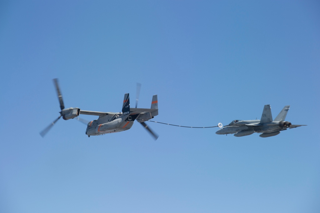
Low Level Air Refueling
An F-4 and KC-135 perform low level air refueling in front of an airshow crowd.
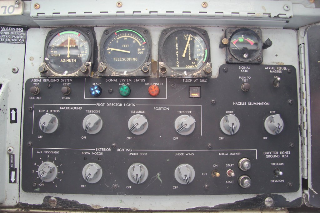
KC-135 Boom Operator Panel
Here is a picture of the boom operator’s panel of the KC-135 stratotanker.
- The gauges at the top indicate the position of the air refueling boom. The green arcs represent the air refueling envelope that the receiver aircraft must remain inside of. The red markings on the gauges are the limits of the air refueling envelope. If the receiver exceeds these limits and the tanker’s signal system is in NORMAL, then an automatic disconnect will occur.
- The boom signal coil voltmeter on the right of the panel shows the status of the boom nozzle signal coil when the PUSH TO TEST button is pressed. The voltmeter displays OPEN, GOOD, and SHORTED.
- The TEST CONTACT button advances the signal system to CONTACT when pressed if the signal amplifier is operational.
- The RESET READY button resets the signal system to READY.
- The blue, green, and orange lights display the current status of the air refueling signal system. The blue READY light indicates the system is ready for contact with a receiver. The green CONTACT light indicates that the boom is in contact with a receiver and that fuel transfer can occur. The orange DISCONNECT light indicates that a disconnect signal has been received.
- The TLSCP AT DISCONNECT (telescope at disconnect) switch selects if the boom will automatically retract when a disconnect signal is received. It has two positions AUTO, and MANUAL.
- The PILOT DIRECTOR LIGHTS are controlled by four rheostats for the background elevation & letters and telescope and for the position elevation and telescope pilot director lights.
- The NACELLE ILLUMINATION rheostats control the brightness of the engine illumination lights.
- The A/R FlOODLIGHT rheostat controls the brightness of the tail mounted air refueling floodlight.
- The BOOM NOZZLE rheostat controls the brightness of the boom mounted nozzle light that shines light on the boom nozzle.
- The UNDER BODY rheostat controls the brightness of lights mounted on the inboard side of the inboard engine struts that illuminate the under body of the aircraft to help with night air refueling.
- The UNDER WING rheostat controls the brightness of lights mounted on the underside of the aft fuselage that illuminage the underside of the wings.
- The BOOM MARKER controls turn on ultraviolet fluorescent tube lights mounted in the boom that cause fluorescent markings on the boom to glow for night air refueling. The ON/OFF switch controls power to the lights and the START positions of the start switch each turn on one of the two fluorescent lights. The neon lights indicate the status of the marker lights.
- The DIRECTOR LIGHTS GROUND TEST switch is used to turn on all pilot director lights at once for maintenance testing.

